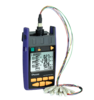
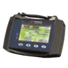
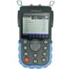
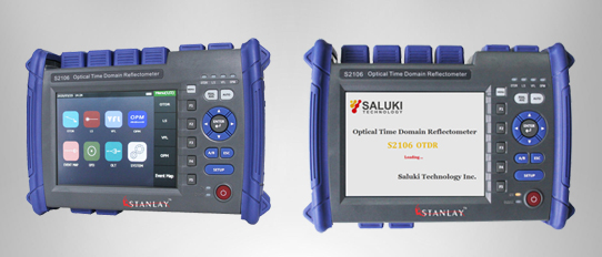
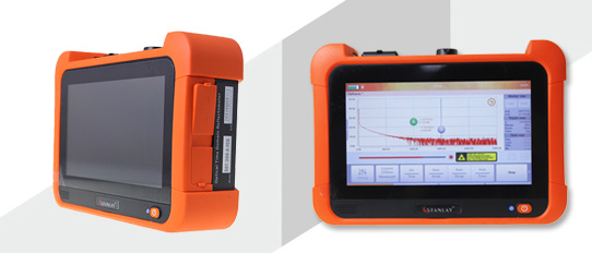
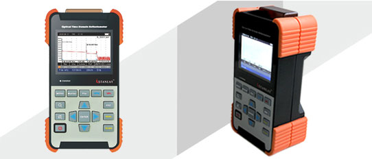
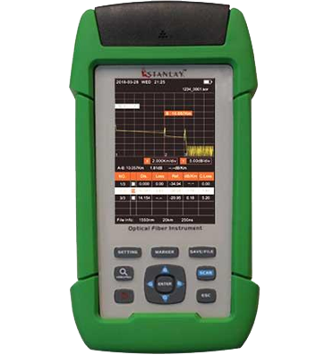
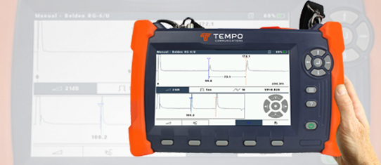
 OTDR
OTDR
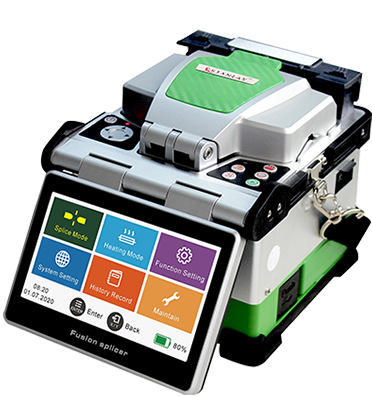
 Fiber Optic Splicing Machine
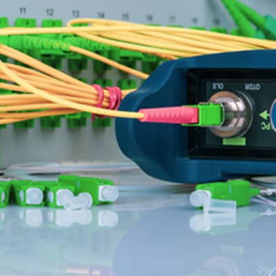
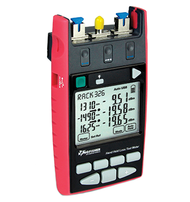
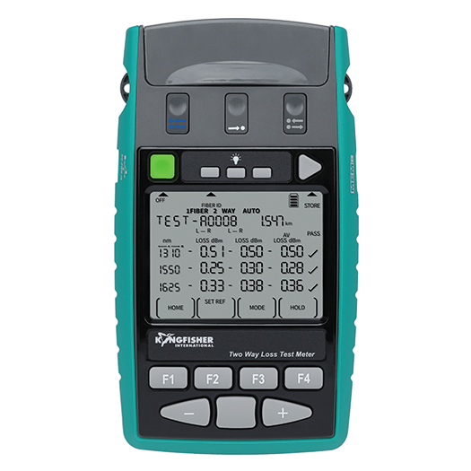
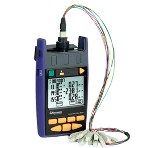
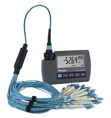
 Optical Loss Test
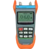
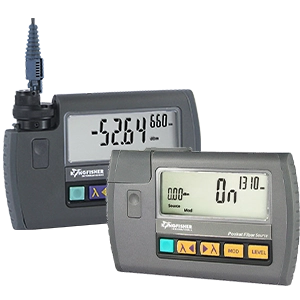
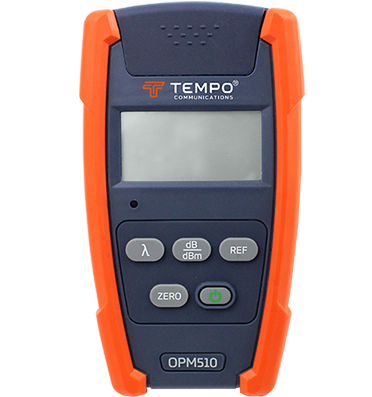
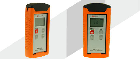
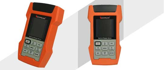
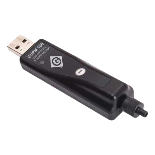
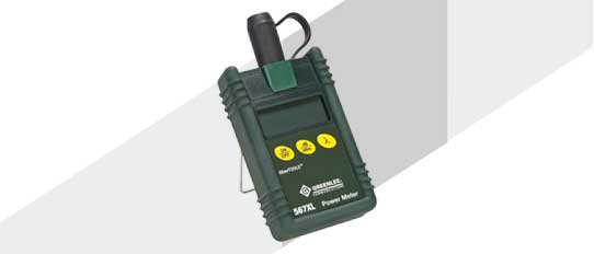
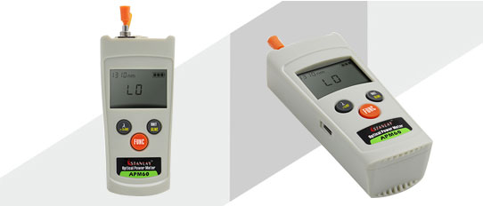
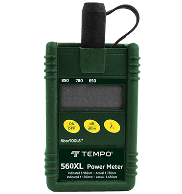
 Optical Power Meters
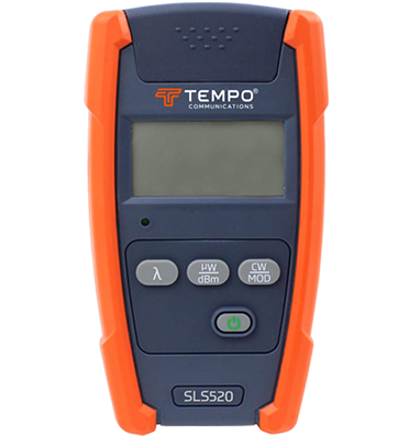
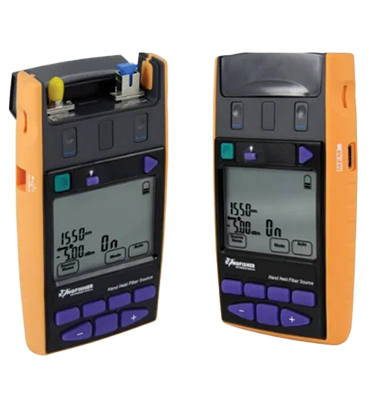
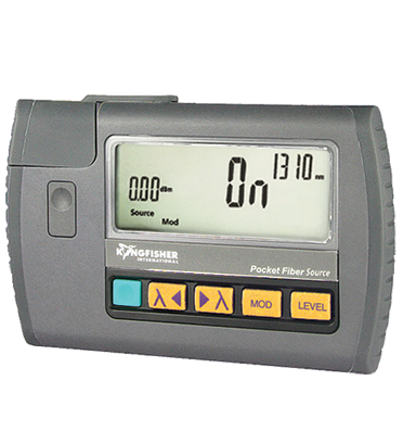
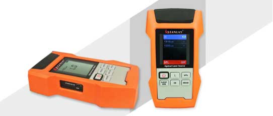
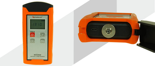
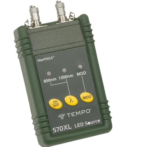
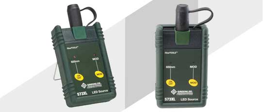
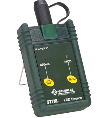
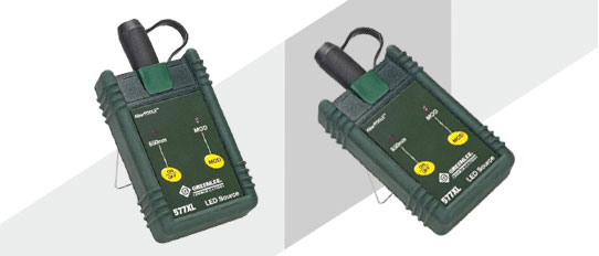
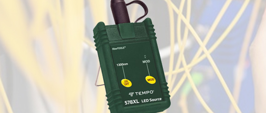
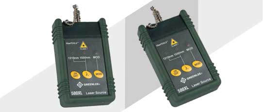
 Optical Light Source
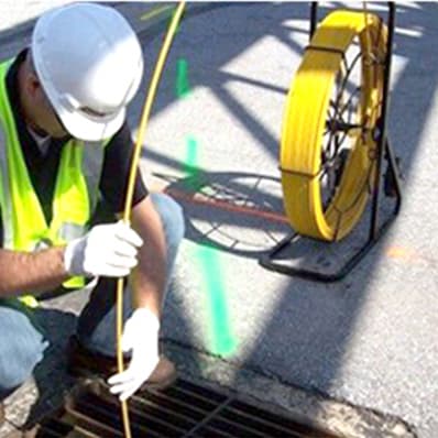
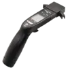
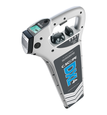
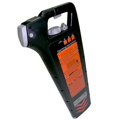
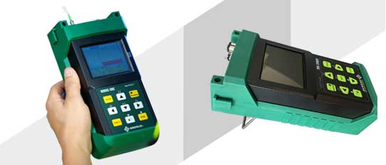
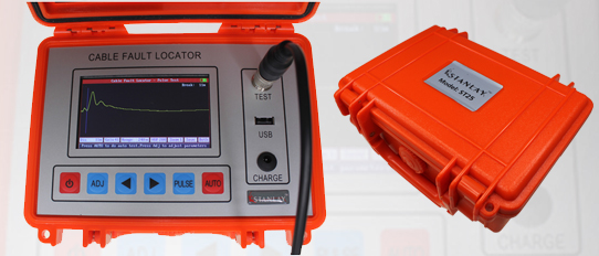
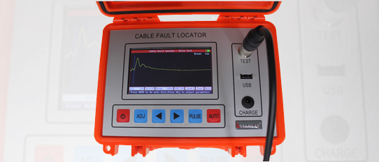
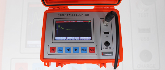
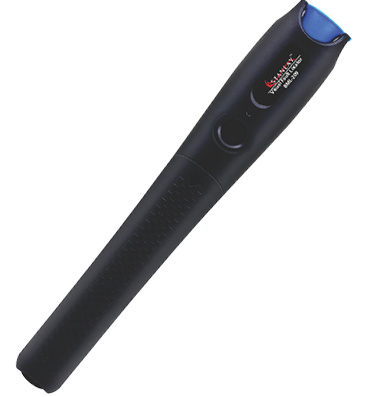
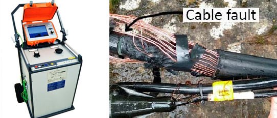
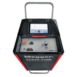
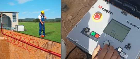
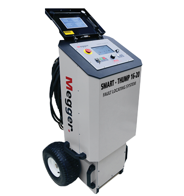
 TDR Cable Fault Locator
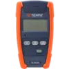
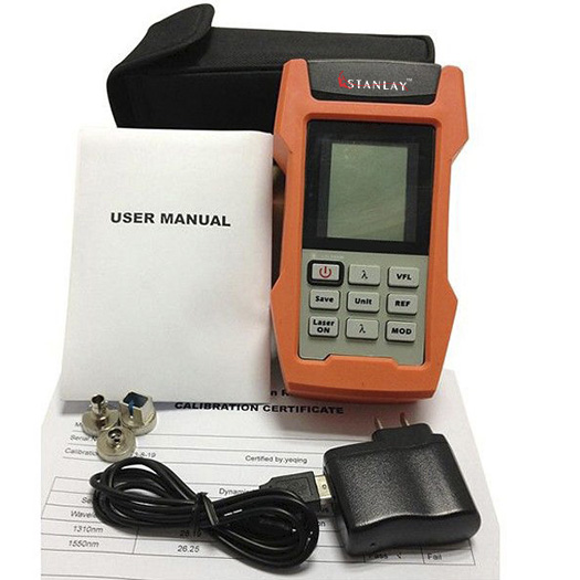
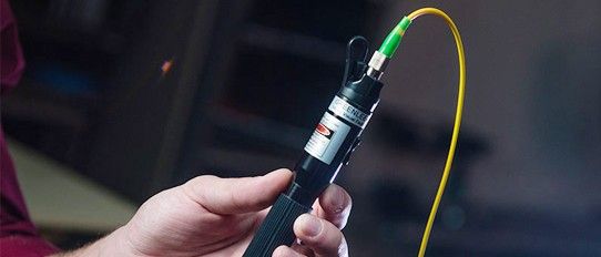
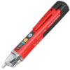
 Fiber Optic Visual Fault Locators
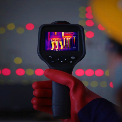
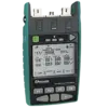
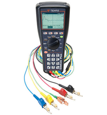
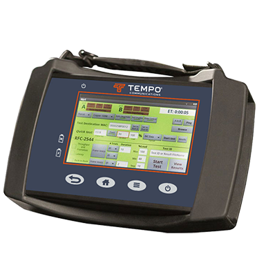
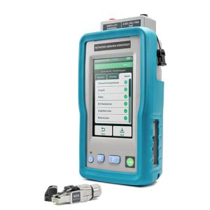
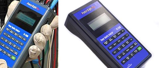
 Network Analyzer
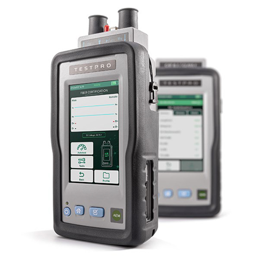
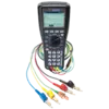
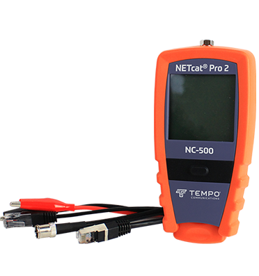
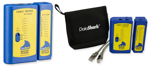
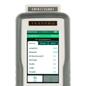
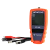 Lan Testers
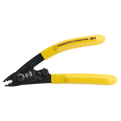
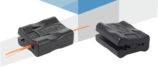
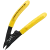 Fiber Tools
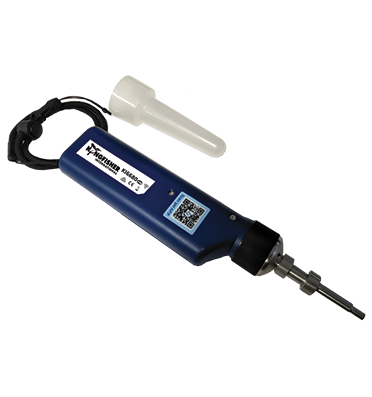
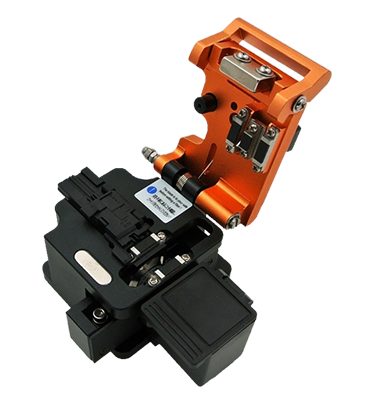
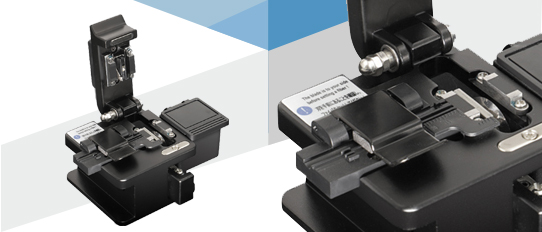
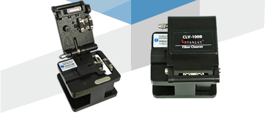
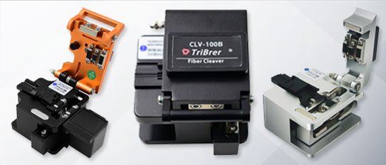
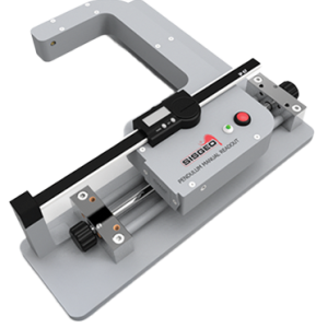
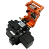 Fiber Cleavers
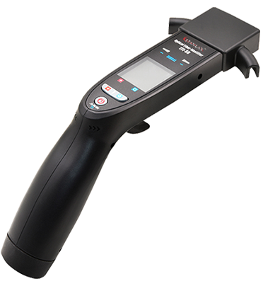
 Optical Fiber Identifier
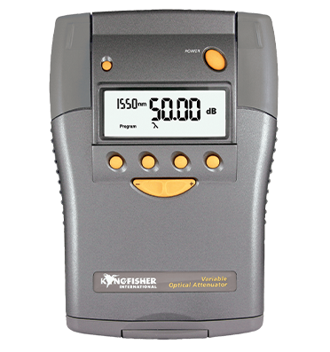
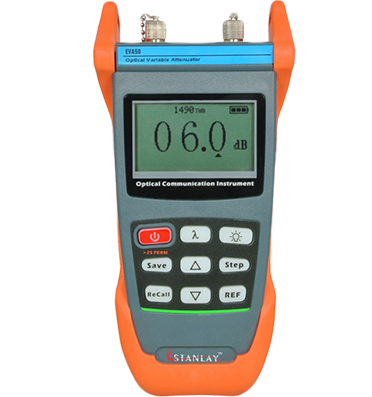
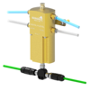
 Fiber Optical Attenuator
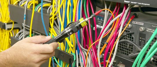
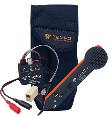
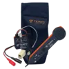 Tone & Probe Kit
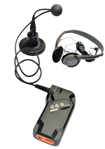
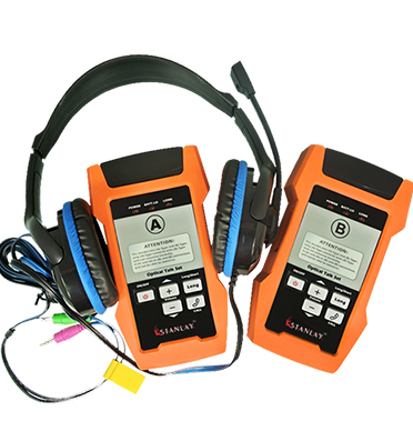
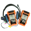 Fiber Optical Talk Set
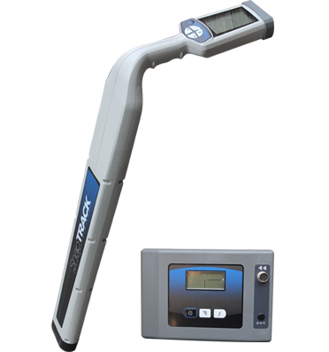
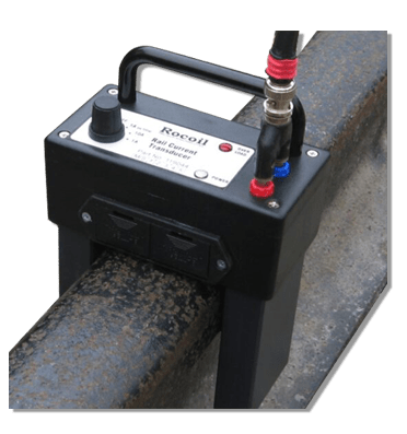
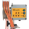
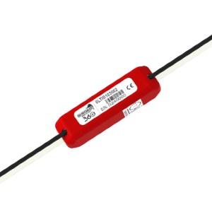
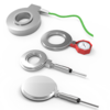
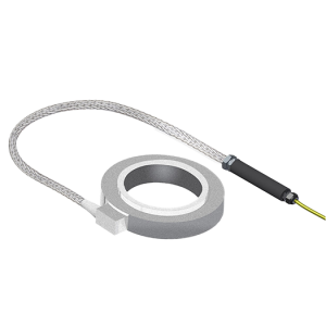
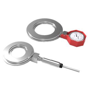
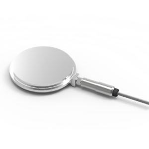
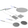
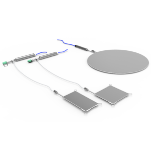
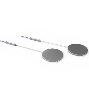
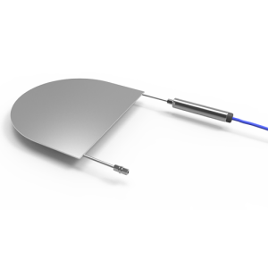
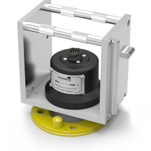
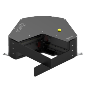
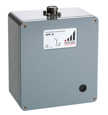
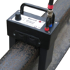 Rocoil Rail Current Transducer
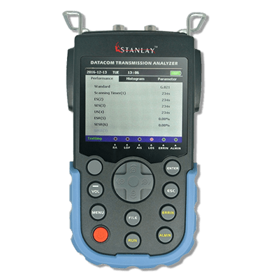
 Bit Error Rate Tester


.png)
.jpg)


.png)


.png)

.png)


.png)


.png)


.jpg)